Low-frequency transformer EI7680 120VAC 176VA
I. DIMENSION(UNIT:mm) 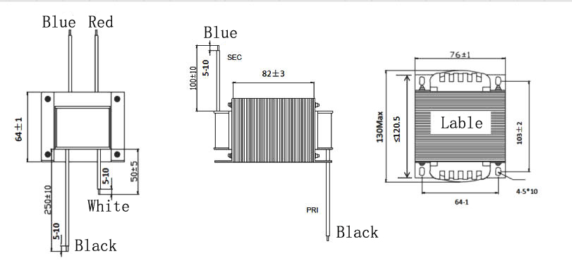
Lable: "EI76*80 120VAC 60Hz" 17.6V 10A STYYWW "YYWW" represents the year and week. For example, 1801 represents the first week of year 18. II. Electrical Schematic Diagram 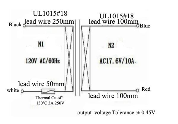
III. Electrical parameters
Enter | Output terminals | Primary loss | No-load current | Open circuit voltage | Load voltage | Load current | Black and White 120VAC 60Hz | Blue-Red | ≤42W | ≤350mA | 18.8VAC ±2% | 17.6VAC ±0.45V | 10Aac |
IV.electrical strength Project | Start | Require | Pressure resistance | Primary to Secondary | 2.5KVAC 0.5m.a.60s | No penetration, no arcing | Primary - Iron Core | 1.5KVAC 1mA 60s | No penetration, no arcing | Secondary core | 0.5KVAC 1mA 60s | No penetration, no arcing |
1.Temperature rise When the ambient temperature is 25℃, the normal operating temperature of the transformer is less than 85℃.
V. Bill of Materials
No. | name Name | Material NameSpecification | model Type | Flame retardant rating Thickness Flame | 1 | Silicon steel sheet | Z11/0.3mm | EI76 | \ | 2 | skeleton | nylon | PA66 | UL-94In | 3 | enameled wire | Polyurethane enameled wire | QZ | ≥155°C | 4 | insulating adhesivebring | Flame-retardant polyester insulating tape | CT* (c)(g) | 130°C | 5 | insulationmembrane | PET | \ | 130°C | 6 | varnish |
| ET-90(a) | 130°C | 7 | Lead-free solder bars | \ | \ | \ | 8 | flux | \ | The 8EB34 | \ | 9 | thermal protector | \ | A4-3A-F | 250V/3A130°C | 10 | lead | \ | UL1015 18AWG |
|
The materials used in this product meet the requirements.ROHSRequirements: The transformer meets the following specifications.CLASS BInsulation system.
Performance Analysis of EI-Type Silicon Steel Laminated Low-Frequency Transformers EI-type silicon steel laminated low-frequency transformers are core components for power frequency (50/60Hz) power conversion and electrical isolation. They are widely used in household appliances, industrial control, lighting equipment, and other fields due to their simple structure, controllable cost, and mature manufacturing processes. Their performance is determined by three core elements: the silicon steel material, the core structure, and the winding design. The following analysis elaborates on key performance dimensions. I. Core Performance Indicators and Influencing Factors 1. Permeability and No-Load Loss
Core Role of Silicon Steel Laminations: EI-type cores use cold-rolled silicon steel laminations (common grades include DW310, DW470). The addition of silicon increases the core's resistivity, reducing eddy current losses. The cold-rolling process aligns the grains directionally, significantly improving permeability (30%~50% higher than hot-rolled silicon steel).
No-Load Loss Characteristics: No-load loss primarily consists of eddy current loss and hysteresis loss.
Eddy current loss is proportional to the square of the lamination thickness. Therefore, EI-type silicon steel laminations are typically made thin (0.35mm or 0.27mm) to further reduce this loss.
Hysteresis loss is related to the coercivity of the silicon steel. Higher-grade cold-rolled silicon steel has lower coercivity and smaller hysteresis loss, making it suitable for applications with high energy efficiency requirements.
Performance Advantage: Under power frequency conditions, EI-type silicon steel cores offer stable permeability, small no-load current (typically <5% of rated current), and low controllable no-load loss, meeting energy efficiency standards for household appliances and low-power industrial equipment.
2. Rated Power and Temperature Rise Characteristics
Core Cross-Sectional Area Determines Power Limit: The rated power of an EI-type transformer is proportional to the square of the center limb's cross-sectional area (approximate formula: P ∝ S²). With the same material, a larger cross-sectional area allows for higher power transmission. For example, an EI48 core is suitable for 50~100W, while an EI66 core can cover the 200~500W power range.
Key to Temperature Rise Control: Temperature rise originates from winding copper loss and core iron loss. The interleaved stacking of "E" and "I" laminations in EI-type cores results in small air gaps and good magnetic circuit closure, leading to uniform iron loss heating. Layered winding facilitates heat dissipation.
Limitation: Compared to toroidal transformers, EI-type transformer cores have joint air gaps, resulting in slightly higher magnetic reluctance. Consequently, for the same power, their temperature rise is slightly higher. Therefore, they are not typically the first choice for high-power applications (>1000W).
3. Voltage Regulation and Load Capacity
Voltage Regulation: This refers to the percentage difference between the output voltage under full load and no-load conditions, reflecting the transformer's voltage stabilization capability under load. The voltage regulation of EI-type transformers is mainly affected by winding resistance and leakage inductance.
Lower winding resistance reduces copper loss and improves voltage regulation. This can be achieved by using thicker wire and shortening the winding length.
Leakage inductance is determined by the distributed inductance of the windings. Employing a "sandwich" winding method (primary-secondary-primary) in EI-type transformers can effectively reduce leakage inductance and improve voltage regulation (typically controlled within 3%~5%).
Load Capacity: Within the rated load range, EI-type silicon steel transformers provide stable output voltage and low waveform distortion (harmonic content <2%), making them suitable for resistive and inductive loads with moderate waveform requirements (e.g., motor drives, relay control circuits).
4. Insulation Performance and Electrical Isolation
Structural Advantage: Insulation layers (such as polyester film, insulating paper) can be easily placed between the core and windings, and between primary and secondary windings in EI-type transformers. Their insulation strength readily meets standards, typically achieving 2500V/1min withstand voltage without breakdown at power frequency, complying with safety standards like IEC and UL.
Application Scenario Suitability: In scenarios requiring isolation between high and low voltage (e.g., household appliance power supplies, industrial control board power supplies), EI-type transformers offer high insulation reliability and safety assurance.
II. Applicable Scenarios and Performance Limitations 1. Optimal Application Scenarios
Low-Power, Power Frequency Domain: Low-power power supplies (e.g., in rice cookers, electric fans, built-in printer power supplies) and control circuit isolation power supplies (e.g., for PLCs, relay control cabinets) operating at 50/60Hz.
Cost-Sensitive Products: The stamping of EI cores and winding processes are mature, leading to low mass-production costs, making them suitable for large-scale applications like household appliances and consumer electronics.
Scenarios Requiring Multiple Outputs: The bobbins of EI-type transformers support multiple winding sets, allowing simultaneous output of different voltages (e.g., 12V, 24V, 5V) to meet multi-load power supply needs.
2. Performance Limitations
Poor High-Frequency Characteristics: The permeability of silicon steel decreases rapidly with increasing frequency. When the frequency exceeds 400Hz, core loss increases sharply, making them unsuitable for high-frequency switching power supplies (ferrite cores are typically chosen for high-frequency applications).
Relatively Large Size and Weight: Compared to ferrite core transformers used in switching power supplies, EI-type silicon steel transformers are larger and heavier for the same power rating, which is disadvantageous for the miniaturization design of portable devices.
Weaker Anti-Electromagnetic Interference (EMI) Capability: Air gaps at the core joints can generate electromagnetic radiation. In scenarios with strict EMI requirements (e.g., medical equipment), additional shielding measures are necessary.
III. Performance Optimization Directions
Upgrade Silicon Steel Material: Use higher-grade cold-rolled grain-oriented silicon steel (e.g., DW230) to reduce no-load loss and improve energy efficiency.
Optimize Winding Process: Adopt the "sandwich" winding method to reduce leakage inductance, and use oxygen-free copper windings to lower resistance, thereby improving voltage regulation.
Improve Core Stacking Method: Increase the core stacking factor (typically ≥0.95), reduce air gaps, and lower magnetic reluctance and core loss.
Enhance Heat Dissipation Design: Add heat dissipation slots to the bobbin or use impregnation processes (e.g., vacuum varnish impregnation) to improve heat dissipation efficiency and reduce temperature rise.
Core Characteristics of EI-Type Silicon Steel Laminated Low-Frequency Transformers EI-type silicon steel laminated low-frequency transformers are one of the most widely used transformer types in the power frequency (50/60Hz) domain. Their characteristics are determined by the core structure, silicon steel material, and process design, and can be divided into advantages and limitations, as detailed below: I. Core Advantages 1. Mature Process, Controllable Cost
EI-type cores are manufactured using stamping processes with a high degree of mold standardization, enabling mass production. Their processing cost is significantly lower than that of toroidal or R-type transformers.
Winding can be completed using automated equipment, without the need for complex core winding or splicing processes. This results in high production efficiency, making them suitable for large-scale applications in cost-sensitive scenarios like consumer electronics and small household appliances.
2. Stable Magnetic Circuit Structure, Strong Electrical Isolation
The interleaved stacking of "E" and "I" silicon steel laminations creates small and uniformly distributed air gaps, resulting in good magnetic circuit closure. This provides stable permeability and a low no-load current (typically ≤ 3%~5% of rated current) at power frequency.
Multiple layers of insulation materials (such as insulating paper, polyester film) can be easily placed between the core and windings, and between primary and secondary windings. This allows insulation withstand voltage ratings to be readily met (conventionally satisfying 2500V/1min), enabling reliable isolation between high-voltage and low-voltage circuits. Safety complies with international standards like IEC and UL.
3. Flexible Multi-Output, High Adaptability
The bobbin of an EI-type transformer has defined winding slots, supporting the winding of multiple windings. This allows for simultaneous output of various voltages (e.g., 5V, 12V, 24V) to meet the power supply needs of multi-load devices, such as household appliance control boards or industrial PLC power supplies.
A wide range of core models is available (e.g., EI35, EI48, EI66, EI96), with different models corresponding to different power ranges (from a few watts to over a thousand watts). This allows for flexible selection based on specific application scenarios.
4. Easy Maintenance, High Reliability
The structure features an open design with good accessibility to the windings and core. In case of faults (e.g., winding short circuit, insulation aging), disassembly for inspection and repair is convenient, without requiring complete replacement.
Excellent temperature resistance. When paired with high-temperature enameled wire and insulating materials, they can operate stably within an ambient temperature range of -20°C to 120°C, adapting to various industrial and commercial operating conditions.
II. Performance Limitations 1. Poor High-Frequency Characteristics, Limited to Power Frequency Applications
The permeability of silicon steel decreases rapidly with increasing frequency. When the operating frequency exceeds 400Hz, core loss (eddy current loss + hysteresis loss) increases sharply, leading to excessive transformer temperature rise and a significant drop in efficiency. Therefore, they cannot be used in high-frequency switching power supplies (ferrite cores are required for high-frequency applications).
2. Relatively Large Size and Weight, Not Conducive to Miniaturization
Compared to switching power supplies or toroidal transformers of the same power rating, EI-type transformer cores have joint air gaps, resulting in slightly higher magnetic reluctance. To achieve the same power, a larger core cross-sectional area and more winding turns are needed, leading to a larger overall size and heavier weight. This makes them unsuitable for portable devices or miniaturized product designs.
3. Energy Efficiency and Temperature Rise Performance Inferior to Toroidal Transformers
Air gaps at the core joints increase magnetic reluctance, leading to slightly higher core loss compared to seamless toroidal transformers. Additionally, the open structure has lower heat dissipation efficiency than the tightly wound structure of toroidal transformers. Consequently, under the same power conditions, EI-type transformers exhibit a relatively higher temperature rise. They are typically not the first choice for high-power applications (>1000W).
4. Relatively Noticeable Electromagnetic Interference (EMI)
Air gaps at the core joints generate a certain degree of electromagnetic radiation. In scenarios with strict EMI requirements (e.g., medical equipment, high-precision testing instruments), additional measures such as shielding enclosures and filter circuits are necessary to meet electromagnetic compatibility (EMC) standards.
Typical Applications of EI-Type Silicon Steel Laminated Low-Frequency Transformers EI-type silicon steel laminated low-frequency transformers, with their mature manufacturing processes, low cost, reliable electrical isolation, and flexible multi-output capabilities, are one of the most widely used transformer types in 50/60Hz power frequency applications. They cover diverse fields including consumer electronics, industrial control, security & lighting, and medical auxiliary equipment. Specific application scenarios and selection key points are detailed below. I. Civil Consumer Electronics Field This is a core application area for EI-type low-frequency transformers, meeting the power supply and electrical isolation needs of various small household appliances and home devices. II. Industrial Control and Automation Field Industrial scenarios impose higher demands on transformer reliability, voltage withstand capability, and multi-output capacity. EI-type transformers can meet the power supply requirements of various control circuits. III. Security and Lighting Field Security equipment requires high power supply stability and concealment, while the lighting field emphasizes cost and compatibility. EI-type transformers can meet these diverse needs. IV. Medical Auxiliary Equipment Field Medical scenarios impose stringent requirements on transformer insulation and low electromagnetic interference. EI-type transformers are suitable only for non-contact diagnostic/auxiliary devices.
Application Products: Auxiliary power supply modules for medical blood pressure monitors, thermometers, portable physiotherapy devices, medical monitors.
Selection Key Points: Use EI-type transformers with high insulation class (Class F or H), with a withstand voltage of 5000V/1min, complying with medical electrical equipment safety standards (e.g., IEC 60601). Employ shielded winding designs to reduce electromagnetic radiation interference with detection signals.
Core Function: Achieves electrical isolation between mains power and medical equipment, preventing patient harm from leakage currents, while also providing stable low-voltage power for detection modules.
|


